|
VISION Documentation |
|
Last update: 05/07/98 |
|
4. DRAWING TOOLS |
Tools parameters can be accessed through the Parameters command in the Options menu.
Defines how drawings on the image will be done. Depending on what is chosen, image pixels will interact with the dots created by the tool used.
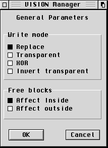 |
Replace Mode: The image pixel is
simply replaced by the dot. Drawings done are opaque. It is
VISION's default drawing mode.
Transparent Mode: The image pixel is replaced only if the new dot is not the same colour as the 0 index colour (usually white), or white in the True Colour mode. Thus, this option gives a transparency effect, since the underlying image can be seen through the white parts of the drawing. XOR Mode: Source and destination are combined in an exclusive or bit to bit operation; all that was white in the drawing becomes transparent, whereas the black parts becomes white if they are put on a black area. Thus, a drawing put astride a black and white area will stay black on the black area and will become white to "emboss" the black area. Invert Transparent Mode: Source and destination are combined by the "not source and destination" bit to bit logical relation. For a black and white drawing, everything that was white becomes black, whereas everything that was black becomes transparent. |
Since version 3.0c, these parameters can be saved in VISION.INI, and
thus be retrieved each time VISION is
launched.
Since version 4.0a, a different type of line for begin and end can be
specified.
Specifies the characteristics of the next text to be inserted. A preview area allows to see in real time the selected text style.
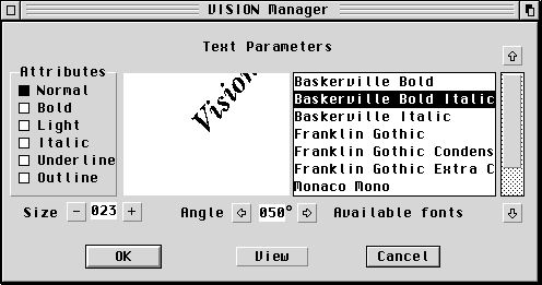
Parameters are:
Since version 3.0c, these parameters can be saved in VISION.INI, and thus be retrieved each time VISION is launched.
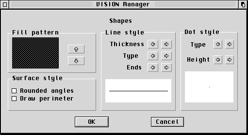
Handles attributes related to lines and surfaces. It is possible to choose:
Since version 3.0c, these parameters can be saved in VISION.INI, and thus be retrieved each time VISION is launched.
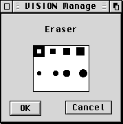 Specifies the size and shape of the eraser. Using
the eraser is the same as using a white brush.
| Function | Draws dots of various types and sizes | |
| Configuration | Clicking on the icon together with the ALT key or a right click displays the shape configuration panel | |
| Modified by | ||
| Note | When moving the mouse quickly, the drawing can become interrupted. Drawing can only be achieved in the image area displayed in the window |
| Function | Draws a continuous line with the mouse | |
| Configuration | Clicking on the icon together with the ALT key or a right click displays the shape configuration panel | |
| Modified by | ||
| Note | Drawing can only be achieved in the image area displayed in the window |
| Function | Draws on the image, using a brush with variable shape and size. | |
| Configuration | Clicking on the icon together with the ALT key or a right click displays the brush parameters panel. It is then possible to choose the shape and the size of the brush | |
| Modified by | ||
| Note |
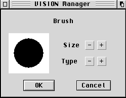 |
The brush has two kinds of
parameters:
|
Since version 3.0c, these parameters can be saved in VISION.INI, and thus be retrieved each time VISION is launched.
| Function | Sprays the selected colour on the image | |
| Configuration | Clicking on the icon together with the ALT key or a right click displays the airbrush parameters panel. It is then possible to choose the density (number of projected dots) and the power (size of the sprayed area) for the tool | |
| Modified by | ||
| Note |
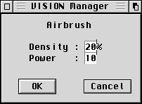 |
The airbrush has two kinds of
parameters:
|
Since version 3.0c, these parameters can be saved in VISION.INI, and thus be retrieved each time VISION is launched.
4.2.5. Connected lines (Klignes)
| Function | Draws a set of broken lines, connected together. Each mouse click sets the end of a line and the beginning of the next one. A right mouse click ends the broken line being created | |
| Configuration | Clicking on the icon together with the ALT key or a right click displays the shape parameters panel | |
| Modified by | ||
| Note | Pressing the Shift key simultaneously forces the line into angles which are multiple of 45 degrees (horizontal, vertical or 45°). A breaking node of the broken line can be situated outside the display window, the resulting line will be drawn in its direction. However, it will not be drawn on the image area which is not visible |
| Function | Draws a line by clicking on the start dot, then by keeping the left mouse button pressed, and releasing it at the desired position | |
| Configuratino | Clicking on the icon together with the ALT key or a right click displays the shape parameters pannel | |
| Modified by | ||
| Note | Pressing the Shift key simultaneously will force the line into angles which are multiple of 45 degrees (horizontal, vertical or 45°). The end of line can be situated outside the display window, the resulting line will be drawn in its direction. However, it will not be drawn on the image area which is not visible |
| Function | Draws an ellipse without filling it. Let the left mouse button pressed until the desired shape is obtained, then put the shape at the desired place with a new click. To cancel the operation, click on the right mouse button | |
| Configuration | None | |
| Modified by | ||
| Note | The display area moves automatically on the image when the circle comes near the window border. It is thus possible to put it at a place which was not visible when it was first created. If the information bar is displayed in the window, vertical and horizontal radiuses are displayed during the drawing. To obtain a perfect circle, these two radiuses should have the same value. Next, when the shape is placed, the information bar displays its x,y position for its bottom right corner |
| Function | Draws a rectangle without filling it. Keep the left mouse button pressed until the desired shape is obtained, then put the shape at the desired place with a new click. To cancel the operation, click on the right mouse button | |
| Configuration | Clicking on the icon together with the ALT key or a right click displays the shape parameters panel | |
| Modified by | ||
| Note | The display area moves automatically on the image when the rectangle comes near the window border. It is thus possible to put it at a place which was not visible when it was first created. If the information bar is displayed in the window, length and height are displayed during the drawing. To obtain a perfect square, these two values should be the same. Next, when the shape is placed, the information bar displays its x,y position for its bottom right corner |
| Function | Draws a filled ellipse. Keep the left mouse button pressed until the desired shape is obtained, then put the shape at the desired place with a new click. To cancel the operation, click on the right mouse button | |
| Configuration | Clicking on the icon together with the ALT key or a right click displays the shape parameters panel | |
| Modified by | ||
| Note | The display area moves automatically on the image when the circle comes near the window border. It is thus possible to put it at a place which was not visible when it was first created. If the information bar is displayed in the window, vertical and horizontal radiuses are displayed during the drawing. To obtain a perfect circle, these two radiuses should have the same value. Next, when the shape is placed, the information bar displays its x,y position for its bottom right corner |
| Function | Draws a filled rectangle. Keep the left mouse button pressed until the desired shape is obtained, then put the shape at the desired place with a new click. To cancel the operation, click on the right mouse button | |
| Configuration | Clicking on the icon together with the ALT key or a right click displays the shape parameters panel | |
| Modified by | ||
| Note | The display area moves automatically on the image when the rectangle comes near the window border. It is thus possible to put it at a place which was not visible when it was first created. If the information bar is displayed in the window, length and height are displayed during the drawing. To obtain a perfect square, theses two values should be the same. Next, when the shape is placed, the information bar displays its x,y position for its bottom right corner |
| Function | Fills a closed surface. Paint will be propagated on all the dots which have the same colour as the dot clicked, if they are not isolated by another colour | |
| Configuration | Clicking on the icon together with the ALT key or a right click displays the shape parameters panel | |
| Modified by | ||
| Note | Be sure to fill a closed surface which is perfectly outlined, otherwise the paint will spread out of the limits |
| Function | Erases the image area located under the mouse cursor | |
| Configuration | Clicking on the icon together with the ALT key or a right click displays the eraser parameters panel | |
| Modified by | Eraser style | |
| Note | Erasing is the same as using the brush with a white colour |
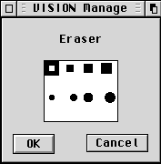 |
The possible styles for the eraser appear in the dialog box. You only need to click on the desired style and to confirm |
| Function | Pastes a text on the image. A first click on the work window opens an entry text area with a maximum of 4 lines of 45 characters each. During the entry, a whole line can be deleted using the Esc key, whereas moving inside the text is done using the arrow cursor keys. A second click allows to paste the text on the image. A click on the Cancel button in the entry area or a right mouse button click during the text positioning will cancel the current entry | |
| Configuration | Clicking on the icon together with the ALT key or a right click displays the text parameters panel | |
| Modified by | ||
| Note | If the whole text does not fit entirely on the displayed area of the image, the hidden part will not be pasted on the image |
| Function | Forward or backward zoom on a part of the image, the centre of the new display being where the zoom has been clicked. A right click increases the zoom factor whereas pressing the Shift key simultaneously decreases it. The possible values are x1, x2, x4, x8 and x16 | |
| Configuration | The zoom factor available through forward/backward successive zooms | |
| Modified by | Shift key | |
| Note | Only the Dot and RGB-Temperature tools are available in zoom mode |
| Function | The RGB-Temperature modifies the selected colour simply by clicking on an image dot having the desired colour. A left click cancels the RGB-Temperature tool. As soon as the function is ended, VISION comes back to the tool selected previously | |
| Configuration | None | |
| Modified by | Nothing | |
| Note | The RGB-Temperature can also be called with the < key. |
| Function | Creates a rectangular table, with the desired number of raws and column. Keep the left mouse button pressed until the desired size is obtained, then put the shape at the desired place with a new click. Then a panel allows to enter the desired number of raws and columns. To cancel the operation, click on the right mouse button | |
| Configuration | Clicking on the icon together with the ALT key or a right click displays the shape parameters panel | |
| Modified by | ||
| Note | Each cell of the resulting table has the same size. The display area moves automatically on the image when the rectangle comes near the window border. It is thus possible to put it at a place which was not visible when it was first created. If the information bar is displayed in the window, length and height are displayed during the drawing. To obtain a perfect square, theses two values should be the same. Next, when the shape is placed, the information bar displays its x,y position for its bottom right corner |
| Function | Moves the image by dragging it with the mouse. As long as the left mouse button is pressed, the image will follow the mouse moves. | |
| Configuration | None | |
| Modified by | Nothing | |
| Note | The Hand can also be called with the Space bar. In this case, as soon as the mouse button is released, the tool selected previously becomes the current tool again |
| Function | Allows to define a rectangular area on the image for edit functions. Keep the left mouse button pressed until the desired area is selected. Moving the displayed area of the image in the window allows to select areas larger than the displayed part. To cancel a selection, single click on the Block tool | |
| Configuration | Clicking on the Block icon (bottom right one) together with the ALT key or a right single click allows to chose between between the rectangular block selection mode, or the lasso, which is a free form selection | |
| Modified by | Selection type | |
| Note | Using the lasso is quite the same as using curves:
while keeping the mouse button pressed, you draw the selection
area on the screen; by releasing the mouse button you can draw
broken lines (a point for each mouse click). To stop the drawing,
click on the right mouse button. The shape is then closed between
the first point inserted and the last. All the options available
for rectangular blocks are available for free form blocks. It is
now possible to have a filter active on the outside of a block
(general parameters). To un-select an area selected with the lasso,
use either the rectangular selection with a single click or, with
the lasso, issue a left click, then, without moving the mouse, a
right click. The selected area is displayed with dotted lines until the selection is moved or cancelled. |
| Function | Allows to select a colour from the palette. A window appears, which displays all the colours available for the current image. Simply clicking on the desired colour will select it | |
| Configuration | None | |
| Modified by | Nothing | |
| Note | In True Colour mode, you have access to the True colour wheel, which contains all the colours for a given brightness. To choose a colour, you must click at the desired place in the colour wheel, or change the current brightness using the cursor located on the right side of the wheel. The selected colour displays on the right of the wheel the values corresponding to the Red, Green and Blue components. The different brightness for the selected colour appear in the rectangle at the bottom |