|
VISION Documentation |
|
Last update: 05/07/98 |
|
2. VISION CONCEPT |
A "bitmap" image is the computer description of a drawing or a picture. An image is made of a set of elementary points called PIXELS. An image is thus a rectangle x pixels wide and y pixels long, the total number of points being x*y (e.g., for a 320 wide pixels and 200 pixels long image, we have 320*200=64000 total pixels). The position of a pixel inside the image is given by its column number x and its line number y relative to the origin x=0 and y=0 located at the top left of the image. Each pixel can take a colour value according to the resolution of the image. For black and white, the point takes a value between two colours, black or white, while in True Colour, each pixel takes a colour value from more than sixteen millions. A pixel from a True Colour image is in fact described by its three components red, green and blue which allow, by mixing them, to obtain more colours than the human eyes can distinguish between.
VISION allows to process images in all the resolutions offered by the ATARI ST and FALCON line, provided the image to be loaded has a number of colours less than the current screen resolution (e.g., on an Atari ST under a screen resolution of 320*200 in 16 colours, only 16, 4 and 2 colours images can be loaded). Another limitation comes from the computer memory. For instance, an image of 640*400 pixels in 16 colours takes 128 K, which is too much to be loaded on 520 ST, which memory is already partially occupied by VISION.
VISION's work screen appears as soon as the program is launched. Every VISION command can be accessed from the menus, tools being also available from a movable window:
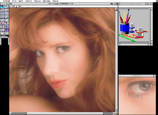
Commands are grouped in 6 menus according to their function. All functions can be directly reached from a keyboard shortcut. This means the command can be reached from a combination of keystrokes. This combination is showed in the menu on the right of the corresponding function. ^S means the Control key and S must be pressed simultaneously, F1 corresponds to the F1 function key, whereas SF1 means the Shift key and the F1 key must be pressed simultaneously.
VISION Menu
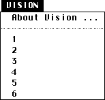 |
About vision ... |
Gives access to the information dialog on the program version and the user name |
Accessory X |
Allows at any moment to use a GEM accessory such as the Control Panel or a calculator |
File Menu
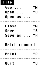 |
New ... (^N) | Creates a blank drawing page in a new window |
| Open ... (^O) | Load an image from the disk with an automatic recognition of the file format | |
| Open as ... | Loads an image from the disk, specifying the file format | |
| Close (^W) | Deletes an image from memory | |
| Save (^S) | Saves the active image keeping its name and format | |
| Save as ... (^R) | Saves the active image after having specified its format and its name | |
| Batch convert ... | Allows an automatic conversion from any format to a given one | |
| Print ... (^P) | Allows to print the current image | |
| Quit (^Q) | Ends the use of VISION. A message warns the user if his work has not been saved |
Edit menu
|
Undo | Cancels the effect of the last command |
| Redo | Redo the last command deleted with the UNDO command | |
| Free undo buffers | Empties the list of cancellable commands | |
| Cut | Stores the current selection in the clipboard and deletes it from the image | |
| Copy | Stores the current selection in the clipboard without deleting it first from the image | |
| Paste | Pastes the clipboard content on the current image | |
| Paste to new page | Pastes to a new image the content of the current selection | |
| Deletes the content of the current selection | ||
| The complete image becomes the current selection | ||
| Invert | Inverts the colours of the current selection | |
| Mirror ... | Applies mirror effects to the current image or selection | |
| Allows to create, modify and view a catalogue of images |
Tools1 Menu
|
Dot (F1) | Draws dot by dot with the chosen shape and height for the selected colour |
| Brush (F8) | Draws with several brush widths and shapes in the selected colour | |
| K-Lines (F2) | Draws broken lines in the selected style and colour | |
| Ellipse (F3) | Draws an ellipse in the selected colour | |
| Filled ellipse (F4) | Create a filled ellipse with the selected pattern and colour | |
| Fill (F5) | Fill an area with the selected pattern and colour | |
| Text (F6) | Inserts a text with the selected size, font and orientation | |
| Temperature (F7) | Take the colour chosen on the drawing as the current colour | |
| Move image (F9) | Move the image according to mouse movements | |
| Palette (F10) | Displays the palette or the colour wheel in True colour to allow to select the current colour |
Tools2 Menu
|
Freehand (SF1) | Draws a continuous curve with the selected thickness and colour |
| Airbrush (SF9) | Draws a cloud of points according to parameters in the selected colour | |
| Line (SF2) | Draws a line with the selected style and colour | |
| Rectangle (SF3) | Draws a rectangle with the selected outline and colour | |
| Filled rectangle (SF4) | Creates a filled rectangle with the selected outline, fill pattern and colour | |
| Eraser (SF5) | Erases. The width of the eraser can be configured | |
| Zoom (SF6) | Increases the zoom factor, or decreases it with shift | |
| Grid-array (SF7) | Creates a table, which outline are in the selected style and colour | |
| Block (SF8) | Creates a current selected area |
Options Menu
|
Full Page (Esc) | Displays the current image in real size on the complete screen |
| Full screen | Displays the complete image, scaled if necessary, on the complete screen | |
| Information (^I) | Gives the main information (RAM used, size, file) on the current image | |
| Convert ... | Allows to transform the number of colours of an image | |
| General (^G) | Setup of the write mode on the current image | |
| Text (^T) | Selection of attribute, size, orientation and font | |
| Shapes (^M) | Selection of dot, line and surface style, and of the fill pattern | |
| Eraser (^E) | Selection of the shape and the size of the eraser | |
| Preferences ... (^F) | Configuration of VISION: paths, number of undo, display | |
| Standard palette standard (Tab) | Switches from the palette of the current image to standard GEM palette |
Extra Menu
|
1/1 (0) | Each point of the image corresponds to a point on the screen. All the tools are available |
| 2/1 (1) | Each point of the image corresponds to 4 points on the screen. Only Dot and Fill are available | |
| (4/1) (2) | Each point of the image corresponds to 16 points on the screen. Only Dot and Fill are available | |
| (8/1) (3) | Each point of the image corresponds to 64 points on the screen. Only Dot and Fill are available | |
| (16/1) (4) | Each point of the image corresponds to 256 points on the screen. Only Dot and Fill are available | |
| Resize ... (^J) | Enlarges or shrinks an image | |
| Rotate ... (^U) | Modifies the orientation of the image | |
| Modifies the brightness of the current image | ||
| Modifies the response curve of the colours | ||
| Palette ... (^D) | Modifies the palette of the current image | |
| Filters ... (^Y) | Filters an image or a block | |
| Displays the presence curves of the colours |
The tools can be chosen in the Tools menus or in the Toolbox. The Toolbox is a window, which contains the main function of VISION as icons. This window can be moved, using the moving bar at the top, in order to put it at a convenient place on the work screen. A tool can be selected by a single click, even is the window is not active. The corresponding icon is then displayed in a lighter colour, and the cursor takes the shape of the tool.
A left click together with the Alternate key or a right click on a tool allows to configure its behaviour. This function is the same as the functions of the Options menu.
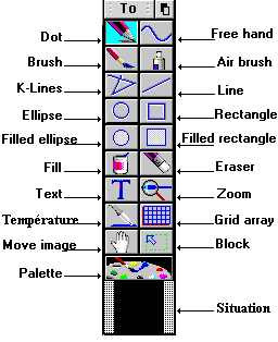 |
This last icon shows the size of the image visible in the window compared with the complete image. The white area corresponds to the complete image, while the black area corresponds to the visible part. If only the black area is visible, it means the complete image is visible. It is possible to move directly the window on the image, by dragging the black area to the desired place, keeping the left mouse button pressed. |
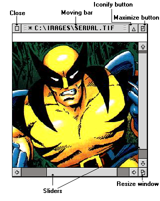
The images appear in standard GEM windows. Clicking inside a window activates it. It then becomes the current working area, and is displayed on top of the other opened windows.
The moving bar allows to change the position of a window without changing its size. It contains the name of the file displayed, preceded by its path. C:\IMAGES\SERVAL.TIF means the window contains the image of the file SERVAL.TIF, which is on the drive C in the IMAGES folder.
When the * symbol is displayed before the file name, it means the modifications made on the screen have not been saved in the file. To do so, you only need to use the Save command in the File menu.
The information bar, when selected in the preferences in the Options menu, displays information related to the current tool, such as: position on the image, size of the object drawn, colour pointed.
A click on the closer erases the image from memory. If modifications have not been saved in the file, VISION asks whether the content of the image should be saved.
A configuration in the preferences in the options menu allows to quit VISION automatically when the last window is closed.
The maximum size button increases the size of the window to fill the screen, letting enough space to display the tools.
A second click on this button brings back the window to its initial size. If the image is not larger than the screen, the maximum size of the window is computed according to the size of the image.
The sliders have the same function as the Move image tool. Cursors correspond to the visible area on screen related to the moving area which corresponds to the size of the image. Moving the display area can be done either by clicking on the arrows, moving the cursor, or a click in the moving area. Since version 3.0c, you can also use the cursor keys to browse the image.
A maintained click on the size button allows to modify manually the size of the window.
Last, the iconify button, available under recent GEM, allows to reduce the window to a size of 80x80 pixels, with a reduced view of the image. A click on the same button restores the initial size. A right click on the iconified window displays a menu with the most used options
Last, a right click on the image displays a popup menu giving a quick access to the following functions:
Open, Maximise, Palette, Information, Save, Save as, Close, Run, LDV
The "Run" function allows to launch another program. If you are under a multi-tasking environment (MultiTOS, MagiC...) this program is launched in parrallel with VISION.
Initially placed at the bottom right of the screen, this window
displays constantly a zoom of the image or even of the graphic screen.
Used together with the mouse arrow cursor, it allows to position precisely
points on an image when using the tools. This window can also be
configured, see